

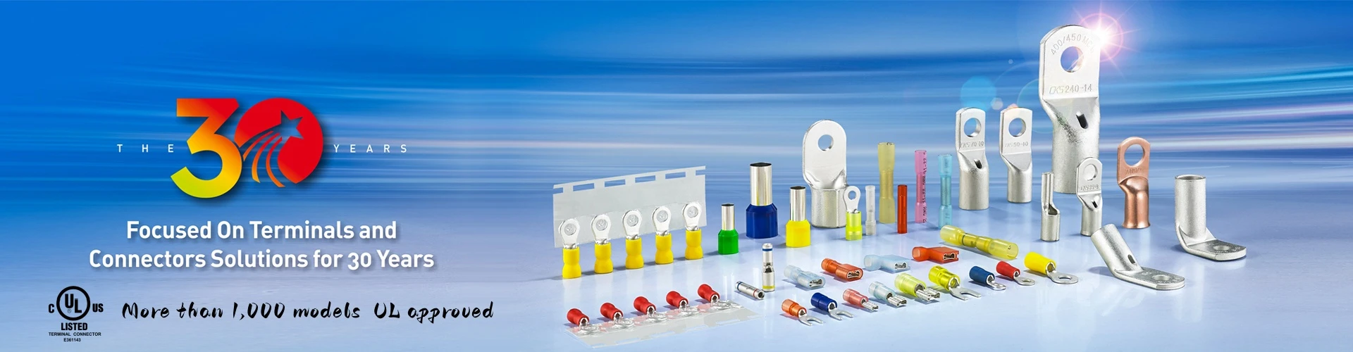
1. What Is a Crimp Terminal?
A crimp terminal primarily relies on mechanical deformation and contact pressure to establish a reliable electrical and mechanical connection.
Unlike a solder terminal, which relies on molten solder to form the connection after cooling, a crimp terminal creates the connection through controlled mechanical compression of the terminal and conductor.
2. Basic Knowledge for Selecting Crimp Terminals
Cable Size: Conductor Cross-Sectional Area (mm²) and AWG
Crimp Terminal Selection Quick Reference Guide - Beginner-Friendly
Understand These Three Terms First
① Terminal Size
This refers to the size of wire that the terminal is designed to accommodate. It is normally specified in mm² (square millimeters).
Generally, the larger the number, the larger the terminal and the larger the conductor it can accommodate.
② Conductor Cross-Sectional Area
This indicates the size of the wire itself. When selecting a terminal, find the range that matches your conductor cross-sectional area.
③ AWG
AWG stands for American Wire Gauge, a standardized wire-sizing system used in the United States.
Important: The smaller the AWG number, the larger the wire. For example, a 2 AWG wire is much larger than a 10 AWG wire.
Terminal Size / Wire Size / AWG Reference
|
Terminal Size (mm²) |
Compatible Wire Size (mm²) |
Approx. AWG |
Typical Application |
|
0.5 |
0.1–0.5 |
22–16 |
Smallest size; signal wires and fine electronic wires |
|
1.5 |
1.5–2.5 |
18–14 |
Small terminals; lighting and low-power appliances |
|
2.5 |
2.5–4 |
14–12 |
Common size; sockets and switch wiring |
|
4 |
4–6 |
14–10 |
Small-to-medium terminals; moderately powered equipment |
|
6 |
6–10 |
12–8 |
Medium size; motors and power wiring |
|
10 |
10–16 |
10–6 |
Medium-to-large size; high-current equipment |
|
16 |
16–25 |
8–4 |
Large size; main circuits in distribution cabinets |
|
25 |
25–35 |
6–4 |
Large size; high-current power distribution |
|
35 |
35–50 |
4–2 |
Extra-large size; main power cables |
|
50 |
50–70 |
1/0 |
Very large size; heavy-duty main cables |
|
70 |
70–95 |
2/0 |
Extra-large size; high-current main cables |
|
95 |
95–120 |
3/0 |
Heavy-duty size; main incoming cables |
|
120 |
120–150 |
250 MCM |
Extra-heavy-duty; large cross-section cables |
|
150 |
150–185 |
300 MCM |
Large industrial power cables |
|
180 |
185–240 |
400 MCM |
Extra-large cables; major engineering projects |
|
240 |
240–300 |
500 MCM |
Very large cables; power plants and heavy industry |
|
325 |
300–400 |
600 MCM |
Maximum-size range; very large conductors |
Selection Tip
First, measure or identify the conductor size → find the corresponding wire-size range in the table → select the appropriate terminal.
Do not select a terminal that is too large, as it may not be crimped tightly enough. Do not select one that is too small, as the conductor may not fit properly.
3. Stud Size and Clearance Hole Size
Stud Size & Clearance Hole Size Chart
Know These Three Things First
① Stud Size
The stud size refers to the diameter of the bolt or screw shank.
Sizes such as #2, #4, and #10 are American screw sizes, while sizes such as 1/4" and 3/8" are fractional-inch bolt sizes.
A larger number or fractional size generally indicates a larger stud diameter.
② Clearance Hole
The clearance hole is the hole through which the bolt or stud passes.
The hole should normally be slightly larger than the stud diameter rather than exactly the same size.
③ How to Read the Chart
Each row shows a matched pair. Find the required stud size on the left, and the recommended clearance-hole size is shown alongside it.
|
Stud Size |
Stud Dia. (mm) |
Stud Dia. (inch) |
Hole Dia. (mm) |
Hole Dia. (inch) |
Quick Note |
|
#2 |
2 |
0.079 |
2.2 |
0.087 |
Smallest size; mini signal terminals |
|
#3 |
2.5 |
0.098 |
2.7 |
0.106 |
Extra-small terminals |
|
#4 |
3 |
0.118 |
3.2 |
0.126 |
Small terminals; low-current wiring |
|
#6 |
3.5 |
0.138 |
3.7 |
0.146 |
Small-to-medium terminals |
|
#8 |
4 |
0.157 |
4.3 |
0.169 |
Common small terminal size |
|
#10 |
5 |
0.197 |
5.3 |
0.209 |
Medium terminal size |
|
1/4" |
6 |
0.236 |
6.4 |
0.252 |
General-purpose standard size |
|
5/16" |
8 |
0.315 |
8.4 |
0.331 |
Medium-to-large terminal |
|
3/8" |
10 |
0.394 |
10.5 |
0.413 |
Large terminal size |
|
7/16" |
11 |
0.433 |
11.5 |
0.453 |
Extra-large terminal |
|
1/2" |
12 |
0.472 |
13 |
0.512 |
Large size; common in power distribution |
|
9/16" |
14 |
0.551 |
15 |
0.591 |
Large-to-extra-large |
|
5/8" |
16 |
0.630 |
17 |
0.669 |
Heavy-duty terminal |
|
11/16" |
18 |
0.709 |
19 |
0.748 |
Extra-large, heavy-duty |
|
3/4" |
20 |
0.787 |
21 |
0.827 |
Very large terminal |
|
7/8" |
22 |
0.866 |
23 |
0.906 |
Jumbo terminal |
|
15/16" |
24 |
0.945 |
25 |
0.984 |
Largest size; high-current terminals |
Pro Tip
Choose the required stud size first, then select the corresponding clearance-hole size.
If the hole is too small, the bolt will not fit. If it is too large, the connection may become loose.
4. Terminal Selection
|
No. |
Terminal Type |
Design Features |
Connection Method |
Typical Applications |
Selection Notes |
|
1 |
Ring Terminal |
Ring-shaped end with a center hole |
Installed over a screw or stud and secured by tightening |
High-reliability applications, industrial equipment, automotive circuits |
Helps prevent pull-out or shifting under wire tension; suitable for large wire sizes and applications where vibration resistance is important |
|
2 |
Spade / Fork Terminal |
Fork-shaped end with two prongs |
Slides under the screw head without completely removing the screw |
Household appliances, test equipment, frequent connection/disconnection |
Approximately 22–10 AWG; fast installation and removal, but may come loose if the screw loosens |
|
3 |
Blade Terminal / Quick-Disconnect Tab |
Flat blade with pressed serrations |
Mates with blade receptacles through push-on or pressure-fit connection |
Timers, motors, valves, relays, mechanical switches, wiring harnesses |
Serrations increase friction and improve retention; suitable where installation space is limited; available in insulated and non-insulated versions |
|
4 |
Hook Terminal |
Hook-shaped end |
Hooked around a screw or stud; requires clearance around the screw |
Applications where the screw cannot be completely removed but sufficient space is available |
Easy to install and helps prevent pull-out; generally not recommended for harsh environments or high-conductivity requirements |
|
5 |
Pin Terminal |
Pin-shaped end |
Inserted into a round mating hole and secured by pressure |
High-density connections and low-current signal transmission, including electronics and PCBs |
Suitable when the mating position is a round hole |
|
6 |
Positive-Lock Terminal |
Locking latch / snap-fit design |
Inserted into a receptacle or connector |
Quick-connect applications |
Automatically locks after insertion, providing retention and protection against accidental disconnection |
|
7 |
Flanged Spade Terminal |
Fork-shaped end with raised flanges |
Slides under the screw head and is secured by tightening |
Applications requiring additional anti-slide-out protection |
The flange helps prevent the terminal from sliding out of the mating position |
|
8 |
Recessed Blade Terminal |
Blade-shaped end with a recess/notch at the tip |
Secured by a screw or plate-type mounting method |
Applications where multiple terminals are mounted on the same screw |
The recessed design makes stacking multiple terminals on one screw more convenient |
|
9 |
Copper Tube Terminal |
Manufactured from high-purity copper tube |
Crimped onto the conductor |
High-current applications |
Provides stable and consistent performance; suitable for high-ampacity applications |
|
10 |
Continuous Terminal Strip (Machine-Applied) |
Multiple terminals connected by a carrier strip |
Automatically fed and crimped by semi-automatic or fully automatic machines |
Mass termination for electronics, PCBs and automated control systems |
Improves production efficiency and crimping consistency |
|
11 |
Butt Connector / Splice |
Tubular splice |
Wire-to-wire connection |
Joining or extending wires |
Provides a more secure and stable connection than simply twisting wires together |
|
12 |
Male/Female Connector (Quick-Disconnect) |
Male and female plug-in pair; semi-insulated or fully insulated |
Push-on plug-in connection |
Low-current applications requiring frequent mating and unmating |
H65 brass or phosphor bronze can be used; phosphor bronze is suitable for frequent mating cycles. A copper sleeve can be added to the barrel when higher pull-out force is required |
|
13 |
Wire Ferrule (Cord End Terminal) |
Tubular sleeve |
Wire is inserted into the ferrule and crimped before installation |
Stranded-wire termination where working space is limited |
Prevents strand fan-out and loose connections; useful when other terminal types cannot fit the installation position |
|
14 |
Copper Cable Lug |
Copper cable lug designed for conductor termination |
Crimped onto the conductor |
Power distribution and high-current electrical connections |
Select according to conductor size, stud size, material, plating and application requirements |
5. Selecting the Right Copper Material and Plating Process
Common Terminal Insulation Options
- Uninsulated Terminal
- PVC Insulated Terminal
- Nylon Insulated Terminal
- Heat-Shrink Insulated Terminal
Uninsulated Terminals
The metal portion is completely exposed and is typically made from copper or tinned copper.
Because the metal is exposed, it may be more susceptible to environmental corrosion.
Temperature resistance:
There is no insulation layer. Temperature resistance mainly depends on the metal and surface plating.
Mechanical protection:
Limited mechanical protection; the exposed metal can be damaged by external forces.
Typical applications:
Suitable for applications requiring high electrical conductivity where environmental conditions are relatively controlled.
PVC-Insulated Terminals
The metal portion is covered by a colored PVC insulation layer.
Color coding, such as red, blue and yellow, helps identify terminal sizes and provides protection against moisture and corrosion.
Typical applications:
Applications requiring insulation protection, moisture resistance and corrosion protection.
Nylon-Insulated Terminals
The metal portion is covered by a colored nylon insulation layer.
Nylon generally provides higher mechanical strength, better impact resistance and greater toughness than PVC.
Typical applications:
High-temperature, high-humidity and corrosive environments, as well as applications requiring improved mechanical strength.
Heat-Shrink Terminals
The metal portion is covered by a colored heat-shrink insulation layer.
After heating, the insulation shrinks tightly around the connection, providing improved sealing and environmental protection.
Typical applications:
High-temperature, waterproof and demanding outdoor environments.
6. Common Mistakes When Selecting Cable Terminals
Inspection Window
The size and design of the inspection window can affect terminal selection.
For applications involving continuous high current, CKS copper tube terminal series can be considered, such as:
- SC - Standard Copper Cable Lug
- SCK - Square Inspection-Window Copper Cable Lug
- DSC - Copper Cable Lug Without Inspection Window
The primary purpose of the inspection window is to make it easier to check whether the conductor has been fully inserted and properly positioned before crimping. It is not necessarily a required feature for every application.
Many customers can successfully use SC terminals with a semi-circular inspection window because the operating current does not exceed the terminal's maximum rated current.
Consider the Actual Application Current
Electrical current can generally be divided into:
- Continuous high current
- Short-duration or transient high current
When selecting a copper cable lug, the customer should provide information about the actual application and operating conditions.
Terminal selection should not be based solely on cost reduction. An inappropriate copper tube or terminal size may result in an unreliable connection.
Even when a terminal is used within its nominal current rating, that does not automatically mean the terminal is suitable for every application.
The nature of the current, duration of the load, conductor size, installation environment and actual application conditions should also be considered.